

Table of Contents
- What is an Electrical Diagram and Why Does It Matter?
- Common Electrical Wiring Diagram Symbols and Their Meanings
At first glance, electrical wiring diagram symbols might look like a foreign language, but with practice, many electrical workers learn to identify and interpret them with ease.
In fields like electrical installation, maintenance and automation, these symbols help electrical technicians communicate clearly, follow safety codes and reduce errors during construction or repair. For those pursuing careers in electrical systems, understanding these symbols is a necessity.
In this blog, we’ll include visuals of the most common electrical symbols, define what they are and include examples of how they’re used. Those interested in this field may benefit from keeping this guide handy.
What is an Electrical Diagram and Why Does It Matter?
An electrical wiring diagram is a visual representation of an electrical circuit or system, showing how components are connected by wires. These diagrams use standardized electrical symbols to represent each component, helping technicians understand how electricity flows through a building or piece of equipment.
Wiring diagrams are important because they provide a clear and accurate roadmap for installing, repairing or troubleshooting electrical systems.
Common Electrical Wiring Diagram Symbols and Their Meanings
On an electrical diagram, symbols represent different electrical components and connections.
For the most part, these electrical symbols are standardized. If they look different than what you’ve seen before, you can look at the diagram legend to help familiarize yourself.
Below, are common electrical symbols you can start familiarizing yourself with:
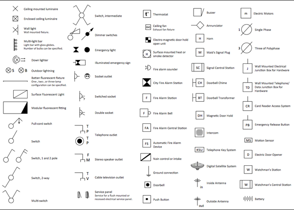
Electrical Symbol Diagram
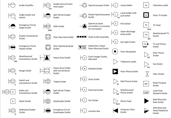
Electrical Outlet Symbol Diagram
How To Read an Electrical Wiring Diagram
Now that you’re familiar with electrical symbols, you can start practicing reading electrical wiring diagrams. Here are some best practices for beginners or anyone preparing to enter the electrical field:
1. Start at the power source
Always begin reading from the power supply or main service panel. This gives you a clear understanding of how electricity flows into the system and what circuits it branches into.
Tip: Look for voltage source symbols (e.g., batteries, transformers or AC supply icons).
2. Follow the flow of current
Trace the diagram in the direction the current flows—from the power source, through conductors and components, and down to the final load (like a light, outlet or appliance). This will help you understand how the circuit functions step-by-step.
3. Learn the common symbols
Familiarize yourself with standard electrical wiring symbols, like switches, resistors, fuses and connection points. Most diagrams include a legend or key, so reference that frequently until you're confident.
4. Identify the circuit type
Determine whether you're looking at a series circuit, a parallel circuit or a combination. This affects how power is distributed and how components interact with each other.
5. Focus on connections
Pay close attention to how wires are connected or not connected. A dot at an intersection usually means wires are joined while crossing lines without a dot means they’re not.
6. Look for control and load sections
In many diagrams, circuits are broken into sections, sometimes referred to as power-passing or power-consuming. For example:
- The control circuit (e.g., switches, buttons, relays) is power-passing.
- The load circuit (e.g., lights, motors, appliances) is power-consuming.
This separation helps when troubleshooting system behavior.
7. Read left to right, top to bottom
Most wiring diagrams are laid out to flow logically from left to right and top to bottom, similar to how a system operates in real time.
8. Use color codes and labels
Diagrams often include wire color codes, labels or numbered lines to show where each wire goes. Always cross-reference these with the legend or notes for full clarity.
9. Refer to the manufacturer’s specifications
If you're working with specific equipment, always check the manufacturer’s wiring diagram, which may include proprietary symbols or layouts.
10. Practice on real diagrams
The more diagrams you study—from residential homes to industrial panels—the better you’ll understand variations and real-world complexity. Electrical wiring courses can teach you to read diagrams and prepare you to apply your knowledge in a professional setting.
Frequently Asked Questions
What are the most common electrical symbols for house wiring?
Some of the most common electrical symbols for residential wiring include switches, outlets, lights, ground wires, resistors, lighting fixtures and circuit breakers.
Are electrical symbols the same for residential and commercial buildings?
Many symbols are the same, but commercial diagrams may include additional components like three-phase power systems, industrial machinery or more complex control systems. When in doubt, reference the diagram legend!
Can I create my own electrical wiring diagram for a home project?
Yes, but it’s important to use the correct electrical symbols and follow local building codes. Working with a licensed electrician or getting training is crucial to ensuring safety and accuracy.
Learn Electrical Wiring Diagram Symbols at Universal Technical Institute (UTI)
If you want to learn more about electrical wiring diagram symbols, UTI’s Electrical, Electronic & Industrial Technology program is a great place to start.130 You’ll learn to interpret complex electrical diagrams, troubleshoot systems and prepare to apply your skills in real-world settings like construction sites or manufacturing plants after graduation! Request more information and an Admission Rep will reach out to hear more about your interest in electrical and answer your questions.
Universal Technical Institute of Illinois, Inc. is approved by the Division of Private Business and Vocational Schools of the Illinois Board of Higher Education.